Salome tut 01
本文最后更新于:2021年10月15日 凌晨
Primitives, partition and meshing example
This sample is known to work on the latest SALOME release.
The compatibility with previous versions of SALOME is not guaranteed, though the sample can work on old versions also.
Objective
Geometric Primitives, tetrahedral and hexahedral 3D meshing, Partitions.
Copyright © EDF R&D 2014.
This tutorial is a part of the EDF internal training course; it does not describe a real use case.
Geometry
- Launch SALOME.
- Create a new study.
- Launch GEOMmodule.
Modeling of 2D object – Usage of primitives
Modification of preferences: (menu File/Preferences). Geometry: Origin and base vectors - check Auto create. Default display mode - Wireframe
Creation of Sketch_1 : (menu New Entity/Basic/2D Sketch).
Click Apply after each consecutive line except for the last one:
Arc First Point (Absolute): (150 ; 0)
Arc (Direction; Perpendicular): (50 ; 115)
Arc (Direction; Tangent): (-100 ; 15)
Line Segment (Direction ; Tangent ; Length) : 150
Line Segment (Direction ; VX-VY ; Y) : (0 ; -1 ;0)
Close dialog
Creation of Mirror_1: (menu Operations/Transformation/Mirror image)
(2nd Constructor)Objects: Sketch_1
Axis Mirror: OX
Leave “Create a copy” checked.
Check the wires: (menu Measures/What is)
=> 1 Wire, 4 Edges, 5 vertices.
Explode into basic elements: (menu New Entity/Explode)
Explode Sketch_1 into Edges.
Explode Mirror_1 into Edges.


Creation of Wire_1: (menu New Entity/Build/Wire)
Select the group of Edges (previously extracted).
Multiple selection is carried out by holding ctrl in the study tree and shift in the viewer.
Creation of Face_1 : (menu New Entity/Build/Face)
Face with Wire_1.Display the result in Shading (popup menu Display Mode/Shading).
Save the study (menu File/Save)
Usage of curves
Explode into sub-elements: (menu New Entity/Explode)
Explode 2 vertices from Face_1 by selection (Select Sub Shapes Vertex)
Selection of a sub-shape is possible only in the OCC Viewer.
Rename the 2 vertices in PB and PA.
Creation of Vertices for the curve : ( New Entity/Basic/Point )
- Vertex_1 (-150, 0, 0), Vertex_2 (-140, 20, 0),
- Vertex_3 (-150, 30, 0), Vertex_4 (-140, 40, 0)
- Vertex_5 (-140, -20, 0), Vertex_6 (-150, -30, 0),
- Vertex_7 (-140, -40, 0)
Creation of Curve_1: (menu New Entity/Basic/Curve)
- Interpolation with the selection of previously created vertexes (3rd Constructor).
- Select just created vertexes in the next order: Vertex_4, Vertex_3, Vertex_2, Vertex_1, Vertex_5, Vertex_6, Vertex_7
Creation of vectors:(menu New Entity/Basic/Vector)
- Vector by 2 vertices (PA and Vertex_4) and (PB and Vertex_7).
Creation of Face_2: (menu New Entity/Build/Face)
- from Curve_1, Vector_1, Vector_2, Edge_1 and Edge_5.
Extrusion: (menu New Entity/Generation/Extrusion)
Extrusion_1 with Face_1 along OZ (Height: 10).
Extrusion _2 with Face_2 along OZ (Height: 10).
Boolean Operation: (menu Operations/Boolean/Fuse)
- Fuse_1 with Extrusion_1 and Extrusion_2.
Creation of 3D Fillet on Fuse_1 : (menu Operations/ Fillet 3D)
- (2nd Constructor) (Just two edges)
- Fillet by selection of edges.
Radius = 25.


Mesh
- Launch module SMESH
Creation of a simple Tetrahedral mesh
- Creation of Mesh_Fillet_1 : (menu Mesh/Create Mesh)
Geometry: Fillet_1
Assign a set of hypotheses -> Automatic Tetrahedralization
Max. Length hypothesis opened, click “Cancel”.
Click 1D Tab, Add “Automatic Length” hypothesis with
Fitness: 0.2
Click OK for validation.
Compute (right-click on Mesh_Fillet_1)
Geometry (Partition)
Launch GEOM module
Partition
Explode Fillet_1 into reference elements: (menu New Entity/Explode)
- Explode into 5 Vertices by selection.
Create 5 Planes: (menu New Entity/Basic/Plane) (1st constructor)
4 planes along vector OX passing through each of 4 first left vertices.
1 plane along vector OY passing through the right vertex.
Creation of the Partition_1:(menu Operation/Partition) (1st constructor)
Partition of Fillet_1 (Objects) with 5 Planes (Tool Object).
Visualize the result in Shading mode with 40% transparency (popup menu).
Meshing (Partition)
Launch SMESH module
Creation of a Tetrahedral mesh from a partition
Creation of Mesh_Partition_Tetra: (menu Mesh/Create Mesh)
Geometry: Partition_1
Automatic Tetrahedralization (Assign a set of hypotheses)
“Max Length” opened, click Cancel
1D, hypothesis “Automatic Length”, Finesse: 0,2
Compute.
Creation of Hexahedral mesh
Creation of Mesh_Partition_Hexa: (menu Mesh/Create Mesh)
Automatic Hexadralization (Assign a set of hypotheses)
Geometry: Partition_1
Number of Segments: 10, Type: Equidistant distribution.
Apply & Close.
Exploding the Edge of Thickness
Activate Geom Module.
Explode one Edge of Thickness
New Entity -> Explode -> Main Object : Partition_1 -> Shape Type : Edge
Activate “Select Subshape” check box and select sub-shape from the viewer.
return to the Mesh Module.
Creation of SubMesh: (menu Mesh/Create Sub-Mesh)
Mesh: Mesh_Partion_Hexa
Geometry : The edge of thickness.
Algo: Wire Discretisation
Hypothesis: Nb Segment (1, Equidistant distribution)
Add Hyp.: Propagation of 1D Hyp. on opposite edges
Compute.


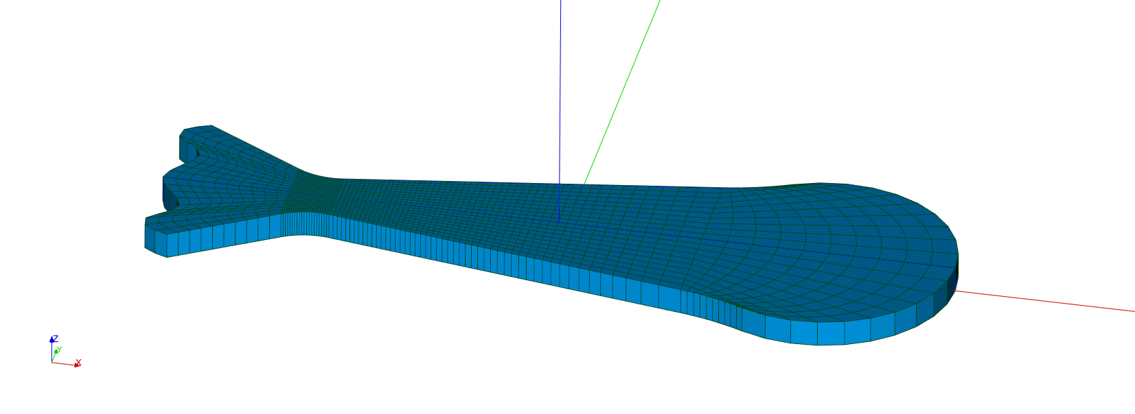
My final mesh

本博客所有文章除特别声明外,均采用 CC BY-SA 4.0 协议 ,转载请注明出处!